BBright™ White Paper
BBright™ Bottom Bracket / Frame / Crank System
By R. Matthews
Aug 25, 2010
1.0
Summary
BBright™ is a new bottom bracket dimensional standard for bicycle frame and cranks. BBright™ provides the best combination of performance and reliability compared to other currently available BB standards. BBright™ does this while maintaining existing chainline and pedal stance width dimensions (sometimes called Q-Factor), thus maintaining compatibility with existing drivetrain standards and riding position. BBright™ also maintains compatibility with existing crank accessories such as crank spider-based power meters. BBright™ requires only a minimum of retooling for crank and frame makers.
2.0
Introduction
The purpose of this white paper is to describe the technical details and the background behind the development of the BBright™ system.
3.0
Background
3.1
A System Approach
In the past, cranks have generally been designed by component manufacturers and bicycle frames have been designed by frame manufacturers. Each of these groups tended to optimize their designs without taking the requirements of the other fully into consideration. In the process of trying to develop the lightest and stiffest bike possible, the developers of BBright™ determined very early on that current crank standards were not ideal to maximize the overall structural efficiency, and neither were frames. Furthermore, it was clear from investigation of available designs, that the two were not optimized to work with each other in the most efficient manner. As a result, the developers of BBright™ decided to go back to the drawing board and use a system analysis approach to make the best improvement in stiffness and structural efficiency.
When a rider pedals a bicycle, the resistance to the movement of the foot (primarily laterally) is the largest contributor to the feeling of pedalling stiffness. For bicycle frames, this is typically characterized by measuring the bottom bracket stiffness in some fashion. One of the frame designer’s goals, then, is to maximize structural properties in order to balance stiffness, weight and other factors.
However, it is clear when looking at real world riding conditions, that the frame is only one part of the load path in the system and all the components that have some effect on stiffness include the shoes, cleats, pedal, crank arms, spider, axle, frame, wheel, tire, etc.. Early experiments showed that the frame and the crankset (which includes the crank arms, spider, chainrings, axle, bearings and connections) both were significant contributors to system stiffness. Due to the fact that the chain is on the right side of the bike, the crankset stiffness is different on both sides. The left side crankset stiffness is driven primarily by axle torsional stiffness, while the right side stiffness is driven primarily by crank arm stiffness (bending and torsion). Axle bending is relatively unimportant, so a longer axle (wider bearing width) decreases axle stiffness. These discoveries lead to the conclusion that significant stiffness gains could not be made without improving the stiffness of both frame and crankset. Furthermore, to make the stiffest system possible, it was clear that both of these components would have to be designed to work together in the best way possible.
3.2
Existing Crankset / Bottom Bracket Technology
Modern high-end cranksets and bottom bracket systems were investigated to determine which gave the best structural performance from both a frame and crank stiffness point of view. Among current road bike systems, there are a number of different standards in the market. These include:
| • | 24mm External Cup
This is the modern ‘standard’ bottom bracket/crank system. It uses a 24mm diameter axle and the bearings are supported in external cups which thread into the frame, which is 68mm wide. |
| • | BB30
This is a newer system which is becoming increasingly popular in road bikes. It uses a 30mm diameter axle and the bearings press directly into the frame. The frame width, however, remains at 68mm, leaving the crank arms cantilevered further from the side of the frame. |
| • | Shimano BB86 Press-In
This system was developed by Shimano and uses the same 24mm axle, crank and bearing position as their external cup system. In this case, bearings are in plastic sleeves which press directly into the frame, allowing the frame width to increase to 86mm. |
| • | SRAM Pressfit30
This is a version of the BB30 system, using the same crank and frame width, but with the bearings being housed in press-in plastic cups, allowing looser frame manufacturing tolerances and improved bearing life. Some other frame manufacturers are also making their own proprietary bottom bracket system similar to this. |
There are various other systems in use on road bikes in limited volume which attempt to address some of these issues, but, for the most part, they do not provide significant stiffness improvements or they require very large cost or standardization impacts on the crank design. Many of these were examined but not considered viable for volume production.
In reviewing test data and riding evaluations of these systems it is apparent that the different systems each have advantages and disadvantages.
For crank design, the key factors to improve stiffness of the bottom bracket/crank design are:
| • | Larger axle diameter |
| • | Narrower bearing support spacing |
For frame design, the key factor to improve stiffness of the bottom bracket/crank design is:
| • | Wider frame members at BB |
For the rider and drivetrain components, the key factors to improve stiffness of the bottom bracket/crank design are:
| • | Pedal stance width unchanged |
| • | Chainline unchanged |
3.3
Discussion of Options
Considering all of the preceding facts, it was apparent that none of the existing systems was fully optimized. In terms of ideal solutions, the best crankset stiffness would be obtained by using the largest axle diameter and the narrowest frame (while leaving pedal stance width and chainline unchanged). For frame stiffness, the widest frame gives the best stiffness. These two requirements are contradictory, so some optimum point must be selected. However, these ideals must be tempered with the realities of mass producing bicycles and using other drivetrain components which are standard. This requires maintaining the existing chainline and using an axle diameter which matches readily available bearings and that crank manufacturers will be willing to make and support. Taking these factors into account, various options presented themselves.
| • | The typical 24mm diameter axle, external cup type bottom bracket system provides the least advantageous system for improving system stiffness, as the axle is small diameter and the frame is also narrow. |
| • | The BB30 standard offers improved axle stiffness, but the reduced frame width limits the frame portion of stiffness. In addition, concerns with the manufacturability of frame for BB30 due to the tight tolerances have been raised. |
| • | Shimano’s BB86 standard offers the most potential frame stiffness improvement, by allowing maximum frame width. However, the right side bearing placement far to the right requires that the bearing be contained in a protrusion in the frame, in order to clear the chain rings. This negates some of the advantages of the wider bearing placement on the right side and is not structurally efficient. The biggest drawback to this system is the smaller axle diameter, which negatively affects crank stiffness. |
| • | SRAM’s PressFit30 standard addresses the frame manufacturability issues of BB30, but the narrow 68mm shell does not help improve frame stiffness. |
In the process of investigating the different options, Finite Element Analysis, hand calculations and parametric optimization were used to evaluate each option and optimize the parameters. These results were then used, along with manufacturability and other produceability factors, to decide on a design option that would give the best stiffness but still meet the other criteria.
4.0
The BBright™ System
4.1
BBright™ Design
From all of the above information, and many more details, the design for BBright™ was chosen as follows. The axle diameter of 30mm was selected to improve the axle and crank stiffness. In order to maximize frame width and stiffness, the left side bearing was moved out from the central plane of the bike by 11mm – effectively the same position as the bearing location in an external cup. This provides the advantage of allowing the frame members to grow to this full width on the non-drive side, significantly improving frame lateral stiffness without affecting clearance. The resulting 79mm axle length is a compromise between 68mm and 90mm axle lengths in existing systems, giving a more optimal overall system solution. Figure 1 compares the potential increase in the widths of frame tubes from a standard 68mm frame to a 79mm BBright™ frame.
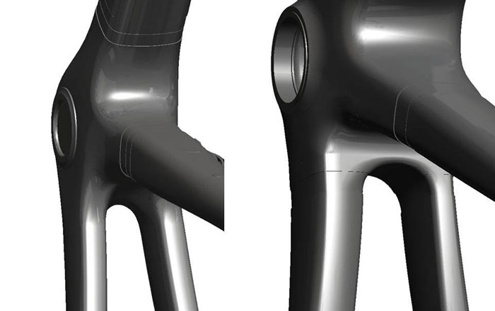
Figure 1 : Frame tube sizes. Left, typical frame tube widths possible with 68mm BB. Right, 11mm wider frame tube sizes possible with BBright™. Wider frame tubes increase the mechanical properties of the frame laterally, increasing stiffness and decreasing weight.
The right side bearing was located at 34mm from the central plane. There were a number of reasons for this. Firstly, moving the larger size bearing out to the same position as the standard external cup bearing on the drive side would have led to interference with the small chainring in some configurations. This would have required a different chainline and incompatibility with existing drivetrain components. Furthermore, this location would have required the bearing to be mounted in a frame protrusion, reducing the structural effectiveness of the frame. Locating the bearing location at 34mm provides space for a straight sided frame structure, for optimum stiffness. Figure 2 shows how standard pedal and chainline positions drive the available volume for the bottom bracket.
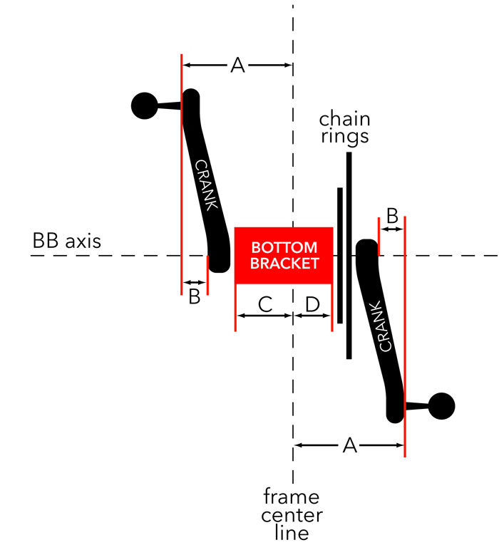
Figure 2 : Available Crank and Frame Design Volume.
| • | Dimension A is half the pedal stance width, which is unchanged from normal cranks in BBright™. |
| • | Dimension B is for ankle clearance, also unchanged. |
| • | Dimension C is 45mm, where 11mm of additional frame width replaces the bearing cup found in external bearing designs, holding the bearing in essentially the same position. |
| • | Dimension D is 34mm. |
| • | The chain rings’ position is unchanged. |
4.2
BBright™: Crank and Frame Interfaces
For crank makers, BBright™ allows use of a 30mm diameter axle. The left side arm is the same as typical arms used with 24mm external cup BBs, with the exception that it must interface to the 30mm axle. Overall, it was determined that this design would be relatively easy for crank manufacturers to make, while still providing improved stiffness in both the axle and frame.
For frame makers, there are currently two implementations of BBright™, discussed below. The
PDF technical drawings give relevant frame dimensions and tolerances for frame manufacturers.
A first frame implementation of BBright™ uses SRAM’s Pressfit30 BB standard to interface with the frame. This choice allows use of a proven bottom bracket design and minimizes risk of bottom bracket/frame issues. The PressFit30’s polymer cups also allow the use of looser frame manufacturing tolerances and give improved bearing life. SRAM supports the BBright™ with their PressFit30-79 Asym. This standard is now published and parts are available from stock. In an emergency, SRAM’s 68mm wide Pressfit30 bottom bracket can also work directly in the 79mm wide BBright™ frames, but the environmental seal on the shorter inner sleeve doesn’t engage.
A second frame implementation of the bottom bracket was also designed. This uses the exact same crank, but the bearings are pressed directly into the frame. This implementation was designed for use on ultra lightweight frames where the extra weight penalty of Pressfit30’s polymer cups would not be acceptable. In this implementation, the bearing seats are molded directly into the frame (or can be designed-in in any fashion desired) and standard size bearings are pressed in to the frame. Any BBright™ crank can then be used directly. This system offers minimum weight, but requires higher precision bearing seats be molded into the frame.
5.0
Conclusions
The new BBright™ system described in this paper has been developed in an attempt to create the most structurally efficient frame/bottom bracket/crank system possible within the limitations of standard drivetrain components and accepted riding positions. This system uses the best attributes of the different currently available bottom bracket designs and combines them with a system-optimal approach to provide the best overall system performance. This design allows frame, bottom bracket and crank designers to improve their components and create a bicycle which provides the best pedaling stiffness with excellent reliability and lowest weight. With this stiffness improvement, frame designers can either make a stiffer frame for the same weight or can make a lighter frame with the same stiffness, or a combination.
For cranks, the BBright™ standard is being produced by different manufacturers, and all are dimensionally interchangeable.
For frames, at least two implementations of the bottom bracket design are possible: Pressfit30 or direct press-in bearings, depending on an individual frame manufacturer’s needs.